|
|
|
|
|
|
|
|

| Information in this document is provided in
connection with Intel products. No license, express or
implied, by estoppel or otherwise, to any intellectual
property rights is granted by this document. Except as
provided in Intel's Terms and Conditions of Sale for such
products, Intel assumes no liability whatsoever, and
Intel disclaims any express or implied warranty, relating
to sale and/or use of Intel products including liability
or warranties relating to fitness for a particular
purpose, merchantability, or infringement of any patent,
copyright or other intellectual property right. Intel
products are not intended for use in medical, life
saving, or life sustaining applications. Intel may make
changes to specifications and product descriptions at any
time, without notice. Copyright (c) Intel Corporation 1997. Third-party brands and names are the property of their respective owners. |
CONTENTS: |
This application note shows optimization techniques used to gain substantial performance improvement on the Inverse Discrete Cosine Transformation (IDCT) and the dequantization in the Joint Photographic Experts Group (JPEG) decompression, running on a Pentium II Processor with MMX(TM) Technology. The code provided in the application note is based on the Independent JPEG Group (IJG) royalty free software. The IDCT and the dequantization are done in one step. The process takes a block of 8x8 frequency components, performs the IDCT and the dequantization on the frequency components. The 'C' code and the MMX(TM) Technology assembly implementation are presented. Performance results for both implementations are summarized. The code provided in this application note is a direct replacement of the IJG royalty free software. Minimum code modification is needed to take advantage of MMX(TM) Technology. Section 5.0 contains all the code listing.
The purpose of JPEG image compression is to reduce the file size required for a given continuous-tone color image and is commonly used in data storage and transmission through the network. The decompression process returns the data back to the approximated original image. JPEG uses the properties of the human eye to achieve 10 to 80 times compression. The JPEG baseline model for image compression consists of four stages: a forward discrete cosine transformation stage (FDCT), a lossy quantization stage, and two lossless coding stages. The baseline model for decompression is the reversal of the image compression: two lossless coding stages, a dequantization stage and the inverse discrete cosine transformation (IDCT) stage. The initial transformation concentrates the information energy into the first few DCT coefficients, the quantizer causes a controlled loss of information, and the two coding stages further compress the data. The YCbCr color space separates luminance(Y) from chrominance(Cb, Cr). The compression algorithm takes advantage of the fact that the human eye is more sensitive to luminance than chrominance. The sensitivity of the eye also increases at low intensity levels. The individual color components in the YCbCr color space are less correlated than in the RGB color space. Therefore this model can be applied to compress each YCbCR component individually.
The Quantization step is used to reduce the magnitude of DCT coefficients and to increase the number of zero value coefficients based on the eye's ability to detect different levels at a given frequency. The values are chosen to match the sensitivity of the eye. Small quantization values are chosen for low frequency and higher values for high frequency coefficients. The JPEG baseline model is considered a "lossy" compressor because the reconstructed image is not identical to the original. Lossless coders, which creates images identical to the original, achieve inferior compression sizes than JPEG.
In preparation of the transformation step, the image is broken up into 8X8 pixels for each color component across the image. Video energy of the 8X8 block is scattered throughout the elements. If the variation of this video energy is slow across the image, a transform is used to concentrate this energy into a few coefficients, 2-dimensional DCT coefficients. Two separate Quantization/Dequantization tables are used, one each for luminance and chrominance. The equation for the quantizer can be written as:
Quantified Coefficients = DCT Frequency Coefficient / Quantizer
The decompression step uses the inverse quantizer:
DCT Frequency Coefficient = Quantified Coefficients * Quantizer
Quantization is the lossy stage in the JPEG coding scheme. If quantization is too coarse, images look "blocky", but if its too fine, more bits are in the final compressed data than is needed. Quantization can be controlled by the Quality Factor, a number which changes the default quantization matrix by an effective multiplicative factor. A lower quality image gives better compression and vice-versa.
Since human eyes are more sensitive to low spatial frequency,
reducing the high spatial frequency information in a given image
results in a compressed file for the image with minimal loss in
visual quality. To accomplish this, FDCT is used to frequency
representation. The data is transformed transform spatial pixel
data into into frequency coefficients of the 8x8 block of pixel
components is transformed into 8x8 block of frequency
coefficients that sinusoidal waveforms. In JPEG, an represents
the amplitudes of reference cosine waves. Notice the compressed
file contains an approximation of the original image since the
high spatial frequency information has been removed. To reproduce
the the compressed data. The IDCT is the process of approximated
original image, the IDCT is applied to transforming the the
spatial pixel data representation of the given image. This
application note is focused on the frequency representation of
the image data back to IDCT process.
For computational simplicity, the 2-dimensional IDCT can be separated into a 1-D row IDCT and a 1-D column IDCT. Several different 1-D algorithms have been developed to perform fast IDCTs. For fast integer computation, IJG JPEG uses the AAN algorithm, and for a more precise integer implementation, the LLM algorithm is used. The following is an explanation of each algorithm.
This implementation is based on an algorithm described in C. Loeffler, A. Ligtenberg and G. Moschytz, "Practical Fast 1-D DCT Algorithms with 11 Multiplications", Proc. Int'l. Conf. on Acoustics, Speech, and Signal Processing 1989 (ICASSP '89), pp. 988-991. The primary algorithm described there uses 11 multiplies and 29 adds. IJG JPEG uses their alternate method with 12 multiplies and 32 adds. The advantage of this method is that no data path contains more than one multiplication; this allows a very simple and accurate implementation in scaled fixed-point arithmetic, with a minimal number of shifts.
This implementation is based on Arai, Agui, and Nakajima's algorithm for scaled DCT. Their original paper (Trans. IEICE E-71(11):1095) is in Japanese, but the algorithm is described in the Pennebaker & Mitchell JPEG textbook. The following code is based directly on figure 4-8 in P&M. While an 8-point DCT cannot be done in less than 11 multiplies, it is possible to arrange the computation so that many of the multiplies are simple scalings of the final outputs. These multiplies can then be folded into the multiplications or divisions by the JPEG quantization table entries. The AAN method leaves only 5 multiplies and 29 adds to be done in the DCT itself. The primary disadvantage of this method is that with fixed-point math, accuracy is lost due to imprecise representation of the scaled quantization values. The smaller the quantization table entry, the less precise the scaled value, so this implementation does worse with high-quality-setting files than with low-quality ones.
The implementation is based on the LLM algorithm. It replaces
each 8-to-8 1-D IDCT step with an 8-to-4 step that produces the
four averages of two adjacent outputs. These steps were derived
by computing the corresponding values at the end of the normal
LLM code, then simplifying as much as possible.
The implementation is based on the LLM algorithm. It replaces
each 8-to-8 1-D IDCT step with an 8-to-2 step producing two
averages of four outputs, for a 2x2 output. These steps were
derived by computing the corresponding values at the end of the
normal LLM code, then simplifying as much as possible.
First step in optimizing is VTune profiling. This step identifies the functions on which to concentrate for the purpose of optimization. Optimizing the highly utilized functions allows better overall performance gain. This section presents many simple optimization techniques used for the the IDCT implementation with an Intel Pentium II Processor with MMX(TM) Technology.
Single Instruction Multiple Data (SIMD) architecture of the MMX(TM) Technology is well suited for the IDCT operation. The smaller the data type used, the more data can be processed in the same pass. IJG JPEG uses "int" data type for the Dequantization table elements. In the Win32 environment, "int" is defined as 32-bit data type. Using the MMX(TM) Technology registers, the most we can do with "int" data type is two data in parallel for the same operation. The actual data requirement for Dequantization table element is 9 bits. By converting the data type to "short", a 16-bit data type, for the Dequantization table, we can increase the parallelism to four data for the same operation. This reduces the IDCT operation of the 8x8 block from 8 passes to only 2 passes. The code in the "jmoreconfg.c":
#define MULTIPLIER int /* type for fastest integer multiply */
is changed to:
#define MULTIPLIER short /* type for fastest integer multiply */
The same holds true for the temporary work space used for the IDCT operation. Changing "int" to "short" data type increases the parallelism to four data for the same operation.
Knowing the maximum and minimum range of your data size helps efficient utilization of the SIMD architecture.
3.2.1 Take Advantage of "pmullw" Instruction
IJG has the input data defined as "short", a 16-bit data type. The dequantization table is also defined as "short". the multiplication of two 16-bit data type values results in a 32-bit value. Below is a code snippet taken from the the IJG code source.
#define DEQUANTIZE(coef,quantval) (((ISLOW_MULT_TYPE) (coef)) * (quantval))
z2 = DEQUANTIZE(inptr[DCTSIZE*2], quantptr[DCTSIZE*2]); //z2 is defined as 32 bits Dword value.
The MMX(TM) Technology optimized IDCT module supports only the 8-bit sample size. The input data is 8-bit signed data and the dequantization table is 9-bit signed data. The maximum data size is a 16-bit signed value for the multiplication of input data by the dequantization value. Utilizing the "pmullw" instruction, four data can be processed at once. This is accomplished with the below instructions:
mov edi, quantptr
mov ebx, inptr
movq mm0, [ebx + 8*2] ; // mm0 = inptr[DCTSIZE*2]
pmullw mm0, [edi + 8*2] ; // mm0 = z2 (16-bit data type)
Above code snippet processes four 16-bit data in parallel. ebx and edi contain pointers to the input data array and quantization table array respectively. Since the end result of the multiplication is a 16-bit value, "pmullw" can be used to the advantage. The "pmullw" instruction performs two operations within three cpu clock cycles. The "pmullw" instruction multiplies two sets of four signed words, producing four double-word as the intermediate results. The low-order word of each intermediate result is then written to the final MMX(TM) Technology register.
3.2.2 Take Advantage of "pmaddwd" Instruction
The "pmaddwd" instruction is another highly leveraged instruction for multiplication and addition in one step. The operation;
#define FIX_1_175875602 ((INT32) 9633)
#define MULTIPLY(var,const) ((var) * (const))
z5 = MULTIPLY(z3 + z4, FIX_1_175875602);
can be accomplished with one SIMD instruction resulted in 4 multiplies and 2 additions:
static __int64 fix_117_117 = 0x25a125a125a125a1;
pmaddwd mm4, fix_117_117 ;
The "pmaddwd" instruction performs two operations within three cpu clock cycles. The "pmaddwd" instruction multiplies two sets of four signed words, producing four double-words as the intermediate results. The two low-order double-words of the intermediate results are added to form the final low-order double-word result. The two hi-order double-words of the intermediate results are also added to form the final hi-order double-word result. The final hi- and low-order double-words are then written to the MMX(TM) Technology register.
"Maximized Parallelism" has the effect of reducing the number of iterations from 8 to 2 passes. For the remaining 2 passes, there exists 50% branch misprediction. For the Pentium II Processor, the penalty of an incorrect prediction is greater than twelve clocks. This is equivalent to a 5% - 10% penalty for the IDCT modules. This penalty is removed by unrolling the loop at the expense of increasing the size of the executable.
Cache Data Alignment is critical to the performance of the Pentium II Processor. A misaligned temporary work space array in the IDCT module can resulted in a 10% - 35% performance penalty for the module. The penalty is eliminated by making sure that the temporary work space array is 8-byte aligned. The code below aligns the wsptr array to 8-byte boundary:
short wsptr[DCTSIZE + 4]; //declare array 8 bytes larger than
is necessary
mov esi, wsptr
add esi, 0x07 ;move the pointer forward 7 bytes
and esi, 0xfffffff8 ;align wsptr to qword
The performance measurements was taken with a 266MHz Pentium II processor system with 32MB memory. MMX(TM) Technology assembly code were compiled using Microsoft Visual C++ 5.0 with the compiler options set to produce Pentium processor code and for maximize speed.
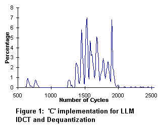
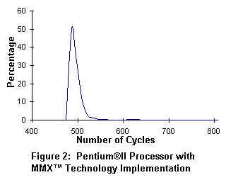
In figure 1, an 8x8 block of IDCT coefficients takes approximately 1500 cpu cycles to process. In figure 2, the Pentium II processor with MMX(TM) Technology requires only 500 cpu cycles to process the same IDCT coefficients. The net performance gain is 3X for the Pentium II processor over the standard 'C' implementation.
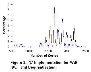
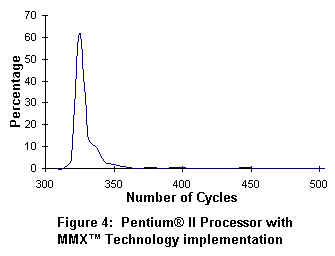
In figure 3, an 8x8 block of IDCT coefficients takes approximately 1600 cpu cycles to process. In figure 4, the Pentium II processor with MMX(TM) Technology requires only 330 cpu cycles to process the same IDCT coefficients. The net performance gain is 5X for the Pentium II processor over the standard 'C' implementation.
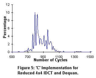
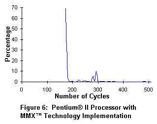
In figure 5, an 8x8 block of IDCT coefficients takes approximately 800 cpu cycles to process. In figure 6, the Pentium II processor with MMX(TM) Technology requires only 180 cpu cycles to process the same IDCT coefficients. The net performance gain is 4X for the Pentium II processor over the standard 'C' implementation.
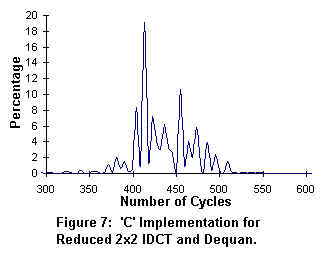
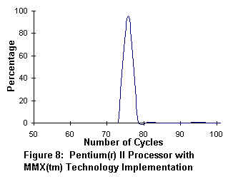
In figure 7, an 8x8 block of IDCT coefficients takes approximately 400 cpu cycles to process. In figure 8, the Pentium II processor with MMX(TM) Technology requires only 77 cpu cycles to process the same IDCT coefficients. The net performance gain is 4X for the Pentium II processor over the standard 'C' implementation.
Free, portable C code for JPEG compression is available from the Independent JPEG Group. Source code, documentation, and test files are included. If you wish to run cjpeg.exe, you need to download the code from the following sites. Version 6a is available from ftp.uu.net:/graphics/jpeg/jpegsrc.v6a.tar.gz. Or if you prefer the ZIP archive format, you can find it at ftp.simtel.net:/pub/simtelnet/msdos/graphics/jpegsr6a.zip.